To view the content, please enable marketing cookies by clicking on the button below.
Cookie settings

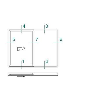
Lift-and-Slide Door 2160 S is made of insulated aluminum profiles with a frame depth of 160 mm and a door leaf depth of 70 mm. The insulation consists of 40 mm wide glass fibre reinforced polyamide strips. The lift-and-slide door has lift-slide fittings for user-friendly handling. The door leaf is easily slid aside and seals all around as the door leaf is lowered a few millimeters in closed position.
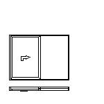
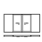
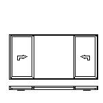
Lift sliding door 2160 S can be performed as one fixed and one sliding door leaf, alternatively with two sliding door leaf. For opening the handle is turned 180° downwards, whereby the door is lifted a few millimeters and can easily be slid aside. When closing the door leaf goes down again and the rubber sealing tightens all around. The door leafs run silently on nylon rollers on a stainless rail and can be parked (lowered) at any position.
Each sliding door leaf is equipped with espagnolette with four anchor points. Handles of aluminium and cylinder locks can be mounted on the inside and outside or inside only.
Handle 
Lift handle, inside 
Lift handle, inside
Pull handle, outside
Lift handle for cylinder lock, inside 
Lift handle for cylinder lock,
inside and outside
Lift handle for cylinder lock, inside
Oull handle, outside
Wheels
For the entire structure to meet the energy saving requirements and ensure good comfort it is necessary to install the sliding terrace door in the warm part of the wall. This means that it should be installed as deep into the wall as possible, which has a number of advantages.
It creates good conditions for appropriate fixing and a well functioning joint. The risk of condensation is reduced due to a higher surface temperature. The joint between the frame profile and the wall shall be made with two step sealing. This means that it should consist of an outer rain barrier with an underlying air channel, a mineral wool insulation layer and an inner diffusion sealing joint.
Unprotected glazed surfaces which are so located that they can be reached by persons shall be designed so as to limit the risk of injury. Such glazed surfaces shall be dimensioned so as to withstand the dynamic influence of a person. Applicable standards and requirements should be taken into account.
Glass thickness 23-53 mm

The illustration shows the different functional dimensions commonly used by the window industry and established by the MTK. The gaskets are made of EPDM rubber and are available in several versions.


Formula for calculating the total U value of a sliding door, taking into account the glazing unit, the share of profiles and an edge zone effect linear factor.
Usliding door = ( Ag * Ug + Af * Uf + Ig * ψg ) / ( Ag + Af )
The calculations are based on the requirements and general guidelines.
Lift-sliding doors must be fixed to a stable and suitable wall structure. The choice of fixing method depends on the wall type. The number and location of fixing points depends on the size of the door.
Example:
Fixing of frame with twist anchor inwards 
Fixing of frame with twist anchor outwards